>>
Other>>
Others>>
Measurement Methods and Precau...Measurement Methods and Precautions of Coordinate Measuring Technology
The Silicon Review
02 July, 2024
Author:
The Silicon Review Team
While CMMs can attain high precision measurements, they might fall short of fulfilling measurement requirements for specific irregularly shaped precision machined parts. Take, for example, parts with intricately curved surfaces or interior cavities may be difficulty for the probe to reach, thus culminating in an incomplete set of measurement results.
Moreover, CMMs demand particular environmental conditions; factors such as temperature and humidity can significantly affect measurement results. To ensure the measurement accuracy of precision machining parts, this article highlights several precautions in light of the limitations of CMMs in the inspection of complex parts.
Different Measurement Method
1. Point triggered
There are two types of point-triggered measurements: CAD model measurement and unknown quantity model measurement.
The process of CAD model measurement involves comparing the known CAD model measurements with the measured piece imported into the measurement software. The analysis is done based on the information obtained from the pre-planned measurement points, which allows the software to complete the entire measurement process for the CAD model.
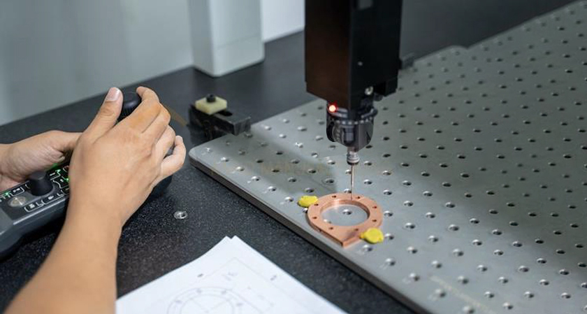
While inspecting the CAD model measurement, the probe swiftly transitions from its original placement to the vicinity of the point to be measured and finally to a position where contact is made with the part to be measured. As such, it should be guaranteed that the detection distance surpasses the contact distance since this would determine the separation between the probe and what is being measured. The entire part undergoes measurement as a result of repeating tests upon gauging distances between three points until all are covered.
When the probe makes contact with the surface being measured, it should not move towards the part's surface location. Instead, it should move away; this action will help to minimize error introduced during operation. This is point two that initiates continuous scanning: a three coordinate measurement technology.
2. Continuous scanning
The technique of continuous scanning finds most use when determining how flat or how curved a surface is without using regular point systems. When continuous scanning measurement is used in coordinate-measuring machine (CMM) technology, it obtains the curved points on the surface from actual geometric measurements, breaking down the surface into elements such as straight lines and circles. By increasing the speed of measurement while also obtaining more data points, we can achieve two conflicting goals: one that aims to enhance the effectiveness of the surface measurement process even as another tries to limit time wastage with low output data.
The developers behind this image measurement software understand the importance of balancing precision with efficiency in industrial applications. They design tools that allow manufacturers to optimize quality control without sacrificing valuable production time.
The technique of continuous scanning finds most use to measure a surface is more regular or less curvature of the object. When continuous scanning measurement is used in coordinate-measuring machine (CMM) technology, it obtains the curved points on the surface from actual geometric measurements, breaking down the surface into elements such as straight lines and circles. By increasing the speed of measurement while also obtaining more data points, the goal of improving the efficiency of surface measurement is accomplished.
Speed is a critical factor in the entire scanning process as it significantly impacts measurement accuracy. Thus, prior to initiating continuous scanning measurement, the surveyor must establish an appropriate speed for the measurements based on actual requirements. This is to prevent a scenario where the speed of measurement is too high and consequently compromises the accuracy of the results obtained during the scanning process.
In the surface scanning measurement, the surface is viewed as a set of curves, which can simplify the measurement task. The surveyor will have to make sure that the pre- imulation in the computer is right before embarking on the scanning process. Consequently, the continuous scanning measuring machine will follow specific instructions and scan along a predetermined line. This approach ensures that all measurements are taken correctly and helps to avoid their distortion and invalidity. This is just an overview of what continuous scanning CMM technology is like.
Three Coordinate Measurement Technology Considerations
1. The selection of a three-coordinate measuring machine should be chosen rationally
Typically, the three-axis measuring instrument range should be 650mm × 650mm × 160mm. Adjustment of the accuracy of the test instrument is done properly to ensure that its error does not exceed 0.0005mm; this is aimed at enhancing the instrument work accuracy and precision purposefully without any overestimate.
There is a need for standardisation and rationalisation when testing the mechanical parts involved. You are able to use computer-aided design (CAD) plus other computer software to make sure you carefully analyze the test data related to it. This helps ensure that the data obtained meets the required specifications and standards as calculated using CAD and other computer software with due accuracy.
When utilizing three-axis measuring technology, the measurement personnel need to carry out comprehensive and detailed assembly of mechanical parts. They should also determine the detection content based on the three-axis measuring instrument for mechanical parts assembly.
2. Should pay attention to the construction quality of the coordinate system
The three coordinate measurement technology assembly should be accurately placed to the three-axis measuring machine according to the specific drawings. Also, the surveyor should choose an appropriate diameter and detector in accordance with the provisions of the drawings, and conduct a comprehensive and detailed inspection of the detector.

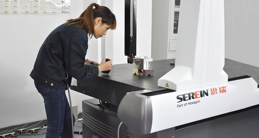
An example can be given by a technology company that developed a fully automatic three standard measuring machine with dimensions of 600mm × 800mm × 600mm and a load capacity of 300kg. In the survey process based on the design drawing box, a 2.5mm long probe was used to determine the Z-axis based on the size of the cylinder in vertical direction. Subsequently, a 6mm long circle was used as a reference point for both X and Y axes, resulting in the establishment of a complete coordinate system. The surveyor could then carry out measurements based on this constructed coordinate system.
3. Attention to the management of the measurement process
When using an advanced three-coordinate measuring instrument, each work must be performed in the specific order of operations to ensure their accuracy and proper coordination with one another.
The personnel measurement should set up a new file on mechanical parts inspection work and its full test. Take the 3-axis tester as an example: it uses a high-resolution camera that demands high lighting conditions. Thus, upon creating the new file, the surveyor needs to configure images to be taken based on specific detection situations—including fine-tuning the light source tightly and adjusting the probing area for each mechanical part detected.
Conclusion
CMM technology is updated due to the continuous progress of science and technology. In the future, CMM will be more intelligent, efficient and accurate. An illustration is a CMM that uses laser interference technology, which helps it attain higher levels of measurement accuracy; in addition to having better anti-interference ability plus faster speed of measurement.